General reference - StruBIM Design

- Introduction
- General information
- Columns schedule
- Walls schedule
- Floor plans
- More information
- Strubim suite. General information
- StruBIM Design. User’s Manual
- StruBIM Design. General reference
- Watch and Learn
- StruBIM Suite (4:41)
- StruBIM Design. 1 NEW PROJECT (2:32)
- StruBIM Design. 2 COLUMN DESIGN (2:18)
- StruBIM Design. 3 WALL DESIGN (2:27)
- StruBIM Design. 4 SLAB DESIGN (2:13)
- StruBIM Design. 5 CONCRETE BEAM DESIGN (2:27)
- StruBIM Design. 6 PUNCHING SHEAR DESIGN (2:04)
- New project from Revit IFC file (5:08)
- StruBIM Dessign. New Features 2017 b (4:22)
- Features of StruBIM versions
- Strubim suite. General information
1. Introduction
StruBIM Design is a tool for the design, checking and editing of structural elements of reinforced concrete, steel, or composites of both steel and concrete based on a structural model and a calculated analytical model.
The structural model can be imported by using a file of XML format or IFC format, either generated from CYPE IFC Builder or other BIM modeling programs. The calculated analytical model is imported from StruBIM ANALYSIS or from an XML file, provided that it contains the necessary information.
StruBIM Design carries out the automatic design and checking of the structural elements, columns, beams, slabs, and walls, and obtains drawing plans according to the needs of the project (Record Engineer).
The program designs and checks the reinforcements of the following types of reinforced concrete elements, according to ACI 318-14, ACI 318-11 and ACI 318-08 code:
- Columns with rectangular or circular cross-sections
- Beams with rectangular cross-sections
- Solid cross-section slabs
- Solid cross-section walls
The program also designs and checks the following types of columns and beams, according to ANSI/AISC 360-10 code:
- I section
- Hollow rectangular section
- Hollow circular section
- Rectangular box
It checks the following types of composite columns, according to ANSI/AISC 360-10 code:
- Rectangular filled with concrete
- Rectangular box of rolled steel plates, filled with concrete
- Circular filled with concrete
- Reactangular with encased section
- Circular with encased section
The program carries out checks of punching shear of slabs on columns without beams. It automatically generates the critical section for each column that transmits stresses to the slab. In this critical section, it verifies the resistance to tangential tension in slabs resisting flexure in both directions.
The results of the automatic design process can be edited and the checking process can be carried out after changes are made, both in reinforced concrete (sections and reinforcements) and in steel sections.
The results of the design can be directly translated into drawing plans of the different elements, columns, beams, slabs and walls, according to the representation needs and project contents (Record Engineer):
- Column schedule
- Beam schedule
- Drawings of slab reinforcement
- Table of punching shear reinforcements
- Wall reinforcement drawings
2. General information
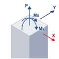
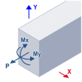
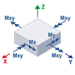
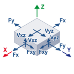
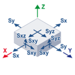
2.1 Sign convention
The following images show the sign convention used for each element, indicating the directions for positive values of each force.
Columns
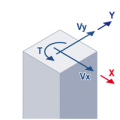
Beams
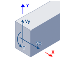
Slabs
2.2 Standards for calculation
For reinforced concrete elements, it is possible to choose between the following codes:
- ACI 318-08
- ACI 318-11
- ACI 318-14
For steel columns and beams, ANSI/AISC 360-10 is used. For composite columns of concrete and steel, ANSI/AISC 360-10 is used in combination with versions 08, 11 and 14 of ACI 318.
2.3 Preferred method for the integration of stresses in 2D elements
For the automatic design and checking of slabs and walls, StruBIM Design processes the results from the analysis based on the finite element method. This analysis produces solutions in specific points of the 2D structure, according to the discretization established. Based on these solutions, necessary values are obtained for automatic design and reinforcement through the generation of integration strips in the 2D element and the calculation of the resultant in the corresponding design section.
The program offers the possibility of calculating the aforementioned resultant by applying either the method of “integration of internal forces” or the method of “integration of nodal forces”.
Commentary about the integration methods:
The first premise is to have available the internal forces and/or nodal forces in the 2D elements being considered for the application of one method or the other. Depending on the source of the analytical model (xml, sbar, etc.), the data available for calculation may vary. It is evident that when we only have one of the two data types available, only the corresponding method can be applied. In the case where both internal forces and nodal forces are available, the user may select which method is appropriate. For guidance, more information about both methods is provided below.
The method of integration of nodal forces provides very good results when the integration strip for the calculation of the resultant extends along the width of the 2D element, independent of the capacity of discretization utilized, as with the case of walls in StruBIM Design. When this method is utilized and the width of the strip is more limited, it is recommended to use a refined discretization of the 2D element.
The method of integration of internal forces provides very good results when the width of the integration strip is more limited, as is the case for the calculation of necessary areas for slabs in StruBIM Design.
2.4 Factor for the distribution of live loads
To take into account the variability of live loading in the design of beams, the program creates automatic load combinations of Live loads and Dead loads. This is applied to factored live loads. For example, if we have defined a combination A (1’2 D + 1’6 L), the beams will be designed with the moments of combination A and an additional combination A’ (1’2 D + factor • 1’6 L). In this additional combination, the design moment of the live load is calculated as if all the beams were pinned.
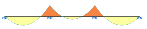
Moments of the live loading with combination A
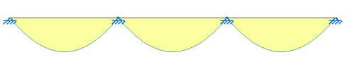
Moments of the live loading with automatic combination A’
3. Columns schedule
This set of tools permits different types of columns to be designed and checked. The information is organized in a table of columns and floors referred to as the Column schedule. A summary check list can be generated of the checks that are carried out. The checks are carried out in each point of defined forces. In this list the resulting worst points are shown. The columns schedule and a drawing of the reference sections are presented in drawings, which can also be generated by the user.
3.1 Concrete columns
The program designs and checks columns with rectangular or circular cross-sections. In rectangular columns, longitudinal and transverse reinforcement may be defined through stirrups. In circular columns, longitudinal and transverse reinforcement may be defined through stirrups/ties or through spirals.
3.1.1 Design properties
The program allows properties of the following to be defined:
- Concrete
- Steel for longitudinal reinforcement
- Steel for transverse reinforcement
- Clear covers
- Unbraced length
The program automatically determines the free length of the column according to the length of the imported bar.
- Effective length factor or Coefficient of buckling around the axis
The value is determined by default equal to 1.
- Nonsway moment factor (δns)
The program calculates δns according to the selected design code, although it allows for editing.
ACI318-08, ACI 318-11 and ACI 318-14
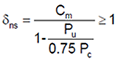
where:
Cm: Moment coefficient. Pu: Applied axial force.

K: Effective length factor
lu: Unbraced length
EIeff=0.25 Ec Ig
Ec: Elastic modulus of concrete
Ig: Moment of Inertia of the gross concrete section, disregarding reinforcement.
It is not possible to determine a vale for δns when Pu ≥ 0.75 Pc , in these cases it is assumed that δns=106
- Moment coefficient (Cm)
The program calculates Cm according to the selected design code, although it allows for editing.
ACI318-08, ACI 318-11 and ACI 318-14
Columns without applied transverse loading between supports:

M1 y M2 are the moments at the ends of the column, M1 being the lesser moment. M1/M2 is negative if the column is in simple curvature and positive if it is in double curvature.
For columns with applied transverse loading between supports:
Cm=1
- Sway moment factor (δs)
Separate factor for each axis. The program assumes that second order effects (P-Δ) have been taken into account in the analysis; therefore, the program determines the value by default δs=1. The factor δs amplifies the moments produced for loading cases such as Wind loads, Seismic loads and Seismic loads (Drift).
- Reduction factor for reducible live loads
Forces in the case of Reducible live loads are multiplied by this factor.
3.1.2 Checks
| Concrete column checks | Chapter | ||
| ACI 318-14 | ACI 318-11 | ACI 318-08 | |
| Design strength ratio | |||
| Flexural and axial strength | 22.4 | 10.3 | 10.3 |
| Shear strength | 22.5 | 11.1 | 11.1 |
| Reinforcement limits | |||
| Minimum longitudinal reinforcement | 10.6.1.1 | 10.9.1 | 10.9.1 |
| Maximum longitudinal reinforcement | 10.6.1.1 | 10.9.1 | 10.9.1 |
| Minimum shear reinforcement | 10.6.2 | 11.4.6.3 | 11.4.6.3 |
| Volumetric spiral reinforcement ratio | 25.7.3.3 | 10.9.3 | 10.9.3 |
| Reinforcement detailing | |||
| Minimum longitudinal reinforcement spacing | 25.2 | 7.6 | 7.6 |
| Minimum spacing of transverse reinforcement | 25.2 | 7.6 | 7.6 |
| Maximum spacing of transverse reinforcement | 25.7.2.1 | 7.10.4.3 | 7.10.4.3 |
| Minimum diameter of tie bar | 25.7.2.2 | 7.10.5.1 | 7.10.5.1 |
| Maximum shear reinforcement spacing | 10.7.6.5.2 | 11.4.5 | 11.4.5 |
3.2 Steel columns
The program designs and checks steel columns of the following types:
- I Section
- Hollow circular section
- Hollow rectangular section
- Rectangular box
3.2.1 Design properties
The program allows properties of the following to be defined:
- Steel
- Unbraced length for flexural buckling
StruBIM Design automatically determines the free length of the column according to the length of the imported bar if the project has been introduced by means of a BIM model.
- Unbraced length for torsional buckling
The program automatically determines the free length of the column according to the length of the imported bar if the project has been introduced by means of a BIM model.
- Effective length factor
Separate factor for buckling around each axis and for torsion. The value is determined by default equal to 1.
- Effective length factor for torsional buckling
The value is determined by default equal to 1.
- Lateral-torsional buckling modification factor (Cb)
The value is determined by default equal to 1.
- Nonsway moment factor (B1)
Separate factor for buckling around each axis in steel columns. The value is determined by default equal to 1.
- Sway moment factor (B2)
Separate factor for buckling around each axis in steel columns. This factor allows moments to be amplified in the cases of Wind loads, Seismic loads and Seismic loads (Drift). The value is determined by default equal to 1.
- Reduction factor for reducible live loads
Forces in the case of Reducible live loads are multiplied by this factor.
3.2.2 Checks
| Steel column checks | Chapter |
| ANSI/AISC 360-10 | |
| Design strength ratio | |
| Tensile strength | Chapter D |
| Compressive strength | Chapter E |
| Flexural strength | Chapter F |
| Shear strength | Chapter G |
| Flexural and compressive strength | H1.1 |
| Flexural and tensile strength | H1.2 |
| Tubular HSS section subject to torsion | H3.1 |
| Tubular HSS section subject to a combination of torsion, shear, flexure and axial loading | H3.2 |
| Member slenderness | |
| Slenderness ratio, L/r | D1 |
| Effective slenderness ratio, KL/r | E2 |
3.3 Composite columns of steel and concrete
The program checks the following types of composite columns:
- Rectangular tubes filled with concrete
- Rectangular box of rolled steel sheets, filled with concrete
- Circular tubes filled with concrete
- Rectangular with encased section
- Circular with encased section
3.3.1 Design properties
The program allows properties of the following to be defined:
- Concrete
- Steel for longitudinal reinforcement
- Steel for transverse reinforcement
- Clear covers
- Steel section material
- Unbraced length for flexural buckling
The program automatically determines the free length of the column according to the length of the imported bar if the project has been introduced through a BIM model.
- Unbraced length for torsional buckling
The program automatically determines the free length of the column according to the length of the imported bar if the project has been introduced through a BIM model.
- Length factor
Separate factor for flexure around each axis. The value is determined by default equal to 1.
- Effective length factor for torsional buckling
The value is determined by default equal to 1.
- Nonsway moment factor (B1)
Separate factor for buckling around each axis in steel columns. The value is determined by default equal to 1.
- Sway moment factor (B2)
Separate factor for buckling around each axis in steel columns. This factor allows moments to be amplified in the cases of Wind loads, Seismic loads and Seismic loads (Drift).The value is determined by default equal to 1.
- Reduction factor for reducible live loads
Forces in the case of Reducible live loads are multiplied by this factor.
3.3.2 Checks
| Checks for composite columns with encased sections | Chapter |
| ANSI/AISC 360-10 | |
| Design strength | |
| Compressive strength | I2.1b |
| Tensile strength | I2.1c |
| Flexural strength | I3.3 |
| Shear strength | I4.1 |
| Flexural and compressive strength | H1.1 |
| Flexural and tensile strength | H1.2 |
| Material limitations | |
| Minimum compressive strength of concrete | ANSI/AISC 360-10, I1.3(1) |
| Reinforcement detailing | |
| Free spacing between the steel core and longitudinal reinforcement | ANSI/AISC 360-10, I2.1e |
| Minimum longitudinal reinforcement spacing |
ACI-11 & 08, 7.6.3 ACI-14, 25.2.3 |
| Minimum spacing of the transverse reinforcement |
ACI-11 & 08, 7.6.1 ACI-14, 25.2.1 |
| Minimum spacing of the transverse reinforcement |
ACI-11 & 08, 7.10.4.3 ACI-14, 25.7.3.1 |
| Maximum spacing of the transverse reinforcement |
ACI-11 & 08, 7.10.5.2 ACI-14, 25.7.2.1 |
| Maximum spacing of the transverse reinforcement |
ACI-11 & 08, 7.10.4.3 ACI-14, 25.7.3.1 |
| Maximum spacing of the transverse reinforcement | ANSI/AISC 360-10, I2.1a(2) |
| Minimum diameter of the sitrrups/ties |
ACI-11 & 08, 7.10.5.1 ACI-14, 25.7.2.2 |
| Minimum diameter of spiral reinforcement |
ACI-11 & 08, 7.10.4.2 ACI-14, 25.7.3.2 |
| Checks for composite columns, hollow sections filled with concrete | Chapter |
| ANSI/AISC 360-10 | |
| Strength of the section | |
| Compressive strength | I2.2b |
| Tensile strength | I2.2c |
| Flexural strength | I3.4 |
| Shear strength | I4.1 |
| Flexural and compressive strength | H1.1 |
| Flexural and tensile strength | H1.2 |
| Tubular HSS section subject to torsion | H3.1 |
| Tubular HSS section subject to a combination of torsion, shear, flexure and axial loading | H3.2 |
| Material limitations | |
| Minimum compressive strength of concrete | I1.3(1) |
| Reinforcement limits | |
| Minimum cross-sectional area of the steel core | I2.2a |
4. Walls schedule
This set of tools permits walls of reinforced concrete to be designed and checked. The information is organized into a table of walls and floors. A summary check list can be generated of the checks that are carried out. The checks are carried out in the transverse section located at the beginning and ending level of each shell that make up the wall. The resulting worst points are shown in this list.
A table of the reinforcement of each wall along with the reference section can be seen in the drawings.
A shear wall can be composed of various sections of different thickness. Each part of the wall can be assigned a different reinforcement strip. In turn, reinforcement can be defined in each reinforcement strip by side or by reinforcement of the confinement (of the column type).
- Face reinforcement: A bar diameter is defined along with a spacing for horizontal and vertical reinforcement, which will be equal for both sides.
- Confinement reinforcement: The number of longitudinal bars for each side and their diameter is defined, as well as a transversal reinforcement composed of closed stirrups and intermediate legs.
The program checks and designs the reinforcement according to the selected type.
4.1 Design properties
StruBIM Design allows properties of the following to be defined:
- Concrete
- Steel for longitudinal reinforcement
- Steel for transverse reinforcmenet
- Clear covers
- Unbraced length
The program automatically determines the unbraced length of the walls according to the designs of the plates which define it if the project has been introduced through a BIM model.
- Effective length factor (k)
The value is determined by default equal to 1.
- Nonsway moment factor (δns)
The program calculates δns according to the selected design code, similar to that carried out with the columns, although it allows for editing.
- Moment coefficient (Cm)
The program calculates Cm according to the selected design code, similar to that carried out for the columns, although it allows for editing.
- Minimum quantity of longitudinal reinforcement (ρl,min)
The program determines the value of ρl,min according to the selected design code, although it allows for editing.
ACI 318-08, ACI 318-11 y ACI 318-14
ρl,min=0.0012 for bars no greater than No. 5 with fy no less than 60,000 psi
ρl,min=0.0015 for all other bars - Minimum quantity of longitudinal reinforcement (ρl,min 1)
The program determines the value of ρl,min 1 according to the selected design code, although it allows for editing.
ACI 318-14: Ec. 11.6.2
ACI 318-11: Ec. 11-30
ACI 318-08: Ec. 11-30
ρl,min1=0.0025+0.5(2.5-hw/Iw)(ρt-0.0025) - Height to length ratio of the wall (hw/lw)
This ratio is used to calculate ρl,min 1; the program automatically determines the value of this ratio with a minimum value of 0.5 ( hw/lw ≥ 0.5).
4.2 Checks
| Checks for walls | Chapter | ||
| ACI 318-14 | ACI 318-11 | ACI 318-08 | |
| Design strength ratio | |||
| Flexural and axial strength | 11.5.2 → 22.4 | 10.3 | 10.3 |
| In-plain shear strength | 11.5.4 | 11.9.2 - 11.9.9 | 11.9.2 - 11.9.9 |
| Out-of-plane shear strength | 11.5.5 → 22.5 | 11.11 | 11.11 |
| Reinforcement limits | |||
| Minimum longitudinal reinforcement | 11.6 | 11.9.8 | 11.9.8 |
| Minimum transverse reinforcement | 11.6.2b | 11.9.9.2 | 11.9.9.2 |
| Reinforcement detailing | |||
| Number of layers | 11.7.2.3 | 14.3.4 | 14.3.4 |
| Spacing of longitudinal reinforcement | 11.7.2 | 11.9.9.5 | 11.9.9.5 |
| Maximum transverse reinforcement spacing | 11.7.3 | 11.9.9.3 | 11.9.9.3 |
5. Floor plans
StruBIM Design permits floor plan elements to be checked and designed, including concrete beams, steel beams, concrete slabs and reinforcements for punching shear in slabs. The beams in the floor plans are organized in the concrete or steel beam schedule
5.1 Beams
Concrete and steel beam design is carried out in the corresponding beam schedule. A summary check list can be generated of the checks that are carried out. The checks are carried out in each point of defined forces. The summary check list shows the resulting worst points. At a minimum, each section of the beam must have at least three points of forces for the checks to be carried out.
In addition to each floor plan, a concrete beams schedule and a steel beams schedule can be added to the drawings.
5.1.1 Concrete beams schedule
5.1.1.1 Detail type for reinforced concrete beams
The reinforcement defined in the columns schedule refers to a previously defined detail type. The program allows the definition of a detail type with different arrangements of reinforcement, for the top reinforcement there is a choice between continuous without additional reinforcement and continuous with additional reinforcement in the supports. For the bottom reinforcement there is a choice between continuous without additional reinforcement, continuous with additional reinforcement at the supports and continuous with additional reinforcement at the mid-span. All beams in each project will contain reference to only one detail type.
5.1.1.2 Continuous beams
The different beam sections arranged about the floor plans can combine to form continuous beams composed of various sections. The additional reinforcements in intermediate supports will pass from one section to another. The program also allows for the automatic generation of continuous beams.
5.1.1.3 Design properties
StruBIM Design allows design properties of the following to be defined:
- Concrete
- Steel for longitudinal reinforcement
- Steel for transverse reinforcement
- Top clear cover
- Bottom clear cover
- Lateral clear cover
- Mechanical cover
The mechanical cover is used during the automatic design phase of reinforcements in order to calculate the necessary areas when there are no defined reinforcements in the beam. In the case in which the beam has arranged reinforcement the mechanical cover will be calculated.
- Torsional moment
In designing for torsion for reinforced concrete structures, two conditions can be identified:
- Torsional moments cannot be reduced by the redistribution of internal forces. This is identified as “equilibrium torsion,” because the torsional moment is required for the structure to be in equilibrium.
- Torsional moment can be reduced by the redistribution of internal forces after cracking if the torsion results from the member twisting to maintain compatibility of deformations.
- Location
It is possible to choose between perimeter and internal beams. The selection of one type or another affects the checking of requirements for structural integrity (ACI 318)
- The program checks to ensure that the continuous top reinforcement of the perimeter beams of the structure is greater than or equal to a sixth of the tensile reinforcement required for negative moments and not less than two bars.
- The program checks to ensure the bottom continuous reinforcement of internal and perimeter beams of the structure is greater than or equal to a quarter of the of the tensile reinforcement required for positive moments and not less than two bars
- Reduction factor for reducible live loads
Forces in the case of Reducible live loads are multiplied by this factor.
5.1.1.4 Checks
| Checks | Chapter | ||
| ACI 318-14 | ACI 318-11 | ACI 318-08 | |
| Design strength ratio | |||
| Flexural strength | 22.3 | 10.3 | 10.3 |
| Shear strength | 22.5 | 11.1 | 11.1 |
| Torsional strength | 22.7 | 11.5 | 11.5 |
| Flexural strength | |||
| Reinforcement limits | |||
| Minimum flexural reinforcement | 9.6.1 | 10.5 | 10.5 |
| Minimum shear reinforcement | 9.6.3 | 11.4.6.3 | 11.4.6.3 |
| Minimum transverse torsional reinforcement | 9.6.4.2 | 11.5.5.2 | 11.5.5.2 |
| Minimum longitudinal torsional reinforcement | 9.6.4.3 | 11.5.5.3 | 11.5.5.3 |
| Reinforcement detailing | |||
| Minimum longitudinal reinforcement spacing | 9.7.2.1 | 7.6.1 | 7.6.1 |
| Maximum longitudinal reinforcement spacing | 9.7.2.2 | 10.6.4 | 10.6.4 |
| Spacing of skin reinforcement | 9.7.2.3 | 10.6.7 | 10.6.7 |
| Longitudinal torsional reinforcement spacing | 9.7.5.1 | 11.5.6.2 | 11.5.6.2 |
| Minimum diameter of longitudinal torsional reinforcement | 9.7.5.1 | 11.5.6.2 | 11.5.6.2 |
| Maximum spacing of shear reinforcement | 9.7.6.2.2 | 11.4.5 | 11.4.5 |
| Maximum spacing of transverse torsional reinforcement | 9.7.6.3.3 | 11.5.6.1 | 11.5.6.1 |
| Minimum size of transverse reinforcement | 9.7.6.4.2 | 7.10.5.7 | 7.10.5.7 |
| Maximum spacing of transverse reinforcement | 9.7.6.4.3 | 9.7.7 | 9.7.7 |
| Structural integrity | 9.7.7 | 7.13.2 | 7.13.2 |
5.1.2 Steel beams schedule
The program designs and checks steel columns of the following types:
- I Section
- Hollow circular section
- Hollow rectangular section
- Rectangular box
5.1.2.1 Design properties
The program allows properties of the following to be defined:
- Steel
- Unbraced length for flexural buckling
The program automatically calculates the unbraced length from the length of the beam and the size of the supports, although it allows for editing.
- Unbraced length for torsional buckling
The program automatically calculates the unbraced length from the length of the beam and the size of the supports, although it allows for editing.
- Effective length factor
Separate factor for buckling around each axis and for torsion. The value is determined by default equal to 1.
- Laterally unbraced length (Lb)
The program automatically calculates the unbraced length from the length of the beam and the size of the supports, although it allows a different length to be defined for the top or for the bottom.
- Lateral-torsional buckling modification factor (Cb)
The value is determined by default equal to 1, although it allows a different length to be defined for the top or for the bottom.
- Nonsway moment factor (B1)
Separate factor for buckling around each axis. The value is determined by default equal to 1.
- Sway moment factor (B2)
Separate factor for buckling around each axis. This factor allows moments to be amplified for Wind loads, Seismic loads and Seismic loads (Drift).The value is determined by default equal to 1.
- Reduction factor for reducible live loads
Forces in the case of Reducible live loads are multiplied by this factor.
5.1.2.2 Checks
| Steel beam checks | Chapter |
| ANSI/AISC 360-10 | |
| Design strength | |
| Tensile strength | Chapter D |
| Compressive strength | Chapter E |
| Flexural strength | Chapter F |
| Shear strength | Chapter G |
| Flexural and compressive strength | H1.1 |
| Flexural and tensile strength | H1.2 |
| Tubular HSS section subject to torsion | H3.1 |
| Tubular HSS section subject to a combination of torsion, shear, flexure, and axial loading | H3.2 |
| Member slenderness | |
| Slenderness ratio, L/r | D1 |
| Effective slenderness ratio, KL/r | E2 |
5.2 Slabs
This toolset permits solid slabs of reinforced concrete to be designed and checked. The checks for strength and minimum longitudinal flexural reinforcement are carried out for each point of forces in the slab. The checks for maximum and minimum spacing are carried out in each group of defined reinforcement, either continuous reinforcement or additional reinforcements.
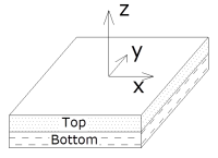
5.2.1 Local axes
The top part of the slab is placed in the positive local Z axis. This consideration should be taken into account when defining the forces of the slab or importing them. When creating a Project from a BIM model it is important to ensure that the local Z axis of the sheet that defines the slab is vertical and with positive upward direction.
When the points that define the slab are arranged in a clockwise direction it is not possible to correctly determine the axes of the structural element; in this case, the program will generate advisement during the import process.
5.2.2 Design properties
The program allows properties of the following to be defined:
- Concrete
- Steel for top reinforcement
- Steel for bottom reinforcement
- Top clear cover
- Bottom clear cover
- Inner layer of reinforcement
5.2.3 Checks
| Slab checks | Chapter | ||
| ACI 318-14 | ACI 318-11 | ACI 318-08 | |
| Design strength | |||
| Flexural strength, X-dir | 8.5.2 → 22.3 | 10.3 | 10.3 |
| Flexural strength, Y-dir | 8.5.2 → 22.3 | 10.3 | 10.3 |
| Out-of-plane shear strength, X-dir | 8.5.3 → 22.5 | 11.11.2 | 11.11.2 |
| Out-of-plane shear strength, Y-dir | 8.5.3 → 22.5 | 11.11.2 | 11.11.2 |
| Reinforcement limits | |||
| Minimum longitudinal reinforcement for flexure | 8.6.1 | 13.3.1 | 13.3.1 |
| Continuous reinforcement | |||
| Minimum longitudinal reinforcement spacing | 8.7.2.1 | 7.6.1 | 7.6.1 |
| Maximum longitudinal reinforcement spacing | 8.7.2.2 | 13.3.2 | 13.3.2 |
5.3 Punching shear
StruBIM Design carries out checks for punching shear of slabs on columns without beams. The program automatically generates the critical section for each one of the columns that transfers stress to the slab. In this critical section, it verifies if the resistance is exceeded against tangential tensions for slabs resisting flexure in two directions.
The program allows the introduction of two types of reinforcements against punching shear: stirrups or headed studs. The strength in the inner and outer perimeters of such reinforcement is verified. As well, the program verifies the geometrical distributions and reinforcements according to the standards of calculation. It can modify the arrangement of the columns if they are interior, edge or on a corner. It can modify the effective slab depth, the maximum and minimum support width, the critical section of both the support and the reinforcement, taking into account gaps and edges, indicating the effective segments opposing punching shear. It can also modify the data for reinforcements such as stirrups/ties and studs.
On the other hand, the stresses of each support can be consulted at the head and base, whose difference provides the punching shear forces that are transmitted to the slab in the floor.
5.3.1 Checks
| Slab punching shear checks | Chapter | ||
| ACI 318-14 | ACI 318-11 | ACI 318-08 | |
| Sections without punching shear reinforcement | |||
| Sectional strength | 22.6.1.3 | 11.11.7.2 | 11.11.7.2 |
| Minimum headed shear stud reinforcement | 22.6.8.3 | 11.11.5.1 | 11.11.5.1 |
| Distance from the column face to the first peripheral line of shear studs | 8.7.7.1.2 | 11.11.5.2 | 11.11.5.2 |
| Spacing between peripheral lines of shear studs | 8.7.7.1.2 | 11.11.5.2 | 11.11.5.2 |
| Spacing between adjacent studs on the peripheral line nearest to the column face | 8.7.7.1.2 | 11.11.5.2 | 11.11.5.2 |
| Section with punching shear reinforcement by means of stirrups | |||
| Sectional strength | 22.6.1.3 | 11.11.7.2 | 11.11.7.2 |
| Minimum effective depth | 22.6.7.1 | 22.6.7.1 | 22.6.7.1 |
| Distance from column face to first stirrup | 8.7.6.3 | 11.11.3.3 | 11.11.3.3 |
| Spacing between stirrups | 8.7.6.3 | 7.6 | 7.6 |
| Spacing between vertical legs of stirrups | 8.7.6.3 | 11.11.3.3 | 11.11.3.3 |
More information
- Strubim suite. General information
- StruBIM Design. User’s Manual
- StruBIM Design. General reference
- Watch and Learn
- StruBIM Suite (4:41)
- StruBIM Design. 1 NEW PROJECT (2:32)
- StruBIM Design. 2 COLUMN DESIGN (2:18)
- StruBIM Design. 3 WALL DESIGN (2:27)
- StruBIM Design. 4 SLAB DESIGN (2:13)
- StruBIM Design. 5 CONCRETE BEAM DESIGN (2:27)
- StruBIM Design. 6 PUNCHING SHEAR DESIGN (2:04)
- New project from Revit IFC file (5:08)
- StruBIM Design. New Features 2017 b (4:22)
- Features of StruBIM versions
Tel. USA (+1) 202 569 8902 // UK (+44) 20 3608 1448 // Spain (+34) 965 922 550 - Fax (+34) 965 124 950